Siemens S7-1200/1500
Requirements
- Siemens Edition or Ultimate Edition
- Siemens S7-1200 or S7-1500 PLC with Ethernet connection
Tutorial: Setting up S7-1200/1500
This driver provides an Ethernet connection to Siemens S7-1200 and S7-1500 PLC.
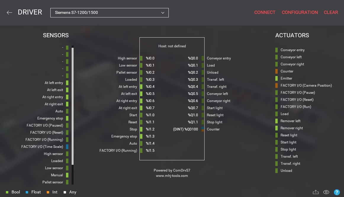
You can export the mapping of scene tags and driver I/O points by clicking on the export button  . Data is exported as TIA Portal compatible xml.
Configuration
| Configuration Setting | Description |
|---|---|
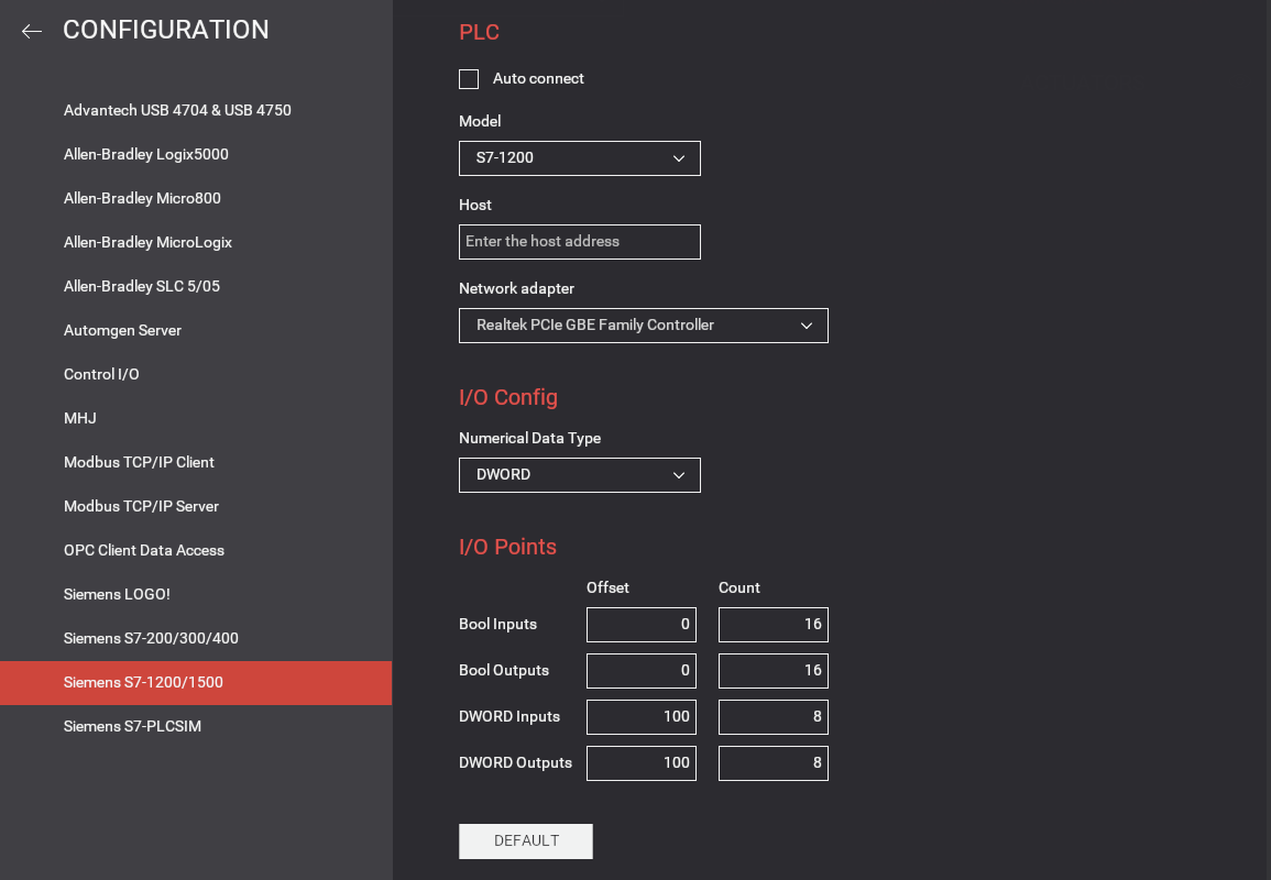
| Auto connect | Periodically tries to connect to the PLC until a successful connection is established. |
| Model | PLC model: S7-1200 or S7-1500. |
| Host | PLC network name or IP address. |
| Network adapter | Network adapter to use. |
| Numerical Data Type | Choose whether WORD or DWORD will be used for analog values. |
| Bool Inputs | Address offset and number of Bool inputs to use for digital sensors (max 256). Sensors' values are written into I memories starting at address 0 (by default). |
| Bool Outputs | Address offset and number of Bool outputs to use for digital actuators (max 256). Actuators' values are read from Q memories starting at address 0 (by default). |
| DWORD Inputs | Address offset and number of DWORD/WORD inputs to use for analog sensors (max 64). |
| DWORD Outputs | Address offset and number of DWORD/WORD outputs to use for analog actuators (max 64). |
| Default | Click to reset to the default options. |
About Analog Values
You should be aware of how floating and integer values are exchanged between Factory I/O and the PLC. The driver can be configured to read/write values using WORD or DWORD and the following list gives you detailed information on how data is encoded/decoded in both cases.
DWORD Inputs (Sensors)
- Floating sensor values are encoded as 32-bit floating point numbers (REAL).
- Integer sensor values are encoded as 32-bit integers.
DWORD Outputs (Actuators)
- Floating actuator values are expected as 32-bit floating point numbers (REAL).
- Integer actuator values are expected as 32-bit integers.
WORD Inputs (Sensors)
- Floating sensor values ranging from -10 V to 10 V are linearized between -27648 and 27648.
- Floating sensor values ranging from 0 V to 10 V are linearized between 0 and 27648.
- Integer sensor values are converted into signed 16-bit integers.
WORD Outputs (Actuators)
- Floating actuator values ranging from -10 V to 10 V are expected to be linearized between -27648 and 27648.
- Floating actuator values ranging from 0 V to 10 V are expected to be linearized between 0 and 27648.
- Integer actuator values are expected as signed 16-bit integers.
When using WORD, conversion between integer values and real number values can be done with the 'SCALE_X' and 'NORM_X' instructions.