Siemens LOGO!
Requirements
- Siemens Edition or Ultimate Edition
- Siemens LOGO! PLC (0BA7 or 0BA8)
Tutorial: Setting up LOGO!
Sample: Pick & Place with LOGO!
This driver provides an Ethernet connection to Siemens LOGO! PLC. It's compatible with 0BA7 and 0BA8 models.

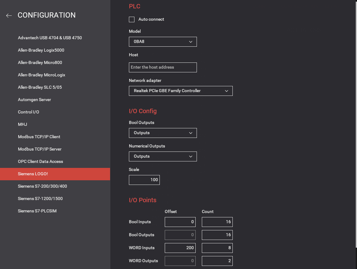
Configuration

| Configuration Setting | Description |
|---|---|
| Auto connect | Periodically tries to connect to the PLC until a successful connection is established. |
| Host | PLC network name or IP address. |
| Network adapter | Network adapter to use. |
| Bool Outputs | Choose from where to read digital actuator values (Q or V memories). |
| Numerical Outputs | Choose from where to read numerical actuator values (Q or V memories). |
| Scale | Floating sensor values are multiplied by this value, actuators are divided by it. For example, an input value of 3.14 with 100 as scale is sent as 314, then it can be divided by the same scale to obtain the real value of 3.14. |
| Bool Inputs | Address offset and number of Bool inputs to use for digital sensors (max 256). Sensors' values are written into V memories starting at address 0 (by default). |
| Bool Outputs | Address offset and number of Bool outputs to use for digital actuators (max 256). Actuators' values are read from V memories starting at address 0 (by default). |
| WORD Inputs | Address offset and number of WORD inputs to use for analog sensors (max 64). Analog sensor values are written into VM memories as integers, starting at address 200 (by default). Note that floating values are multiplied by the scale factor before being written to the PLC. |
| WORD Outputs | Address offset and number of WORD outputs to use for analog actuators (max 64). Analog actuator values are read from VM memories as integers, starting at address 300 (by default). Note that floating values read from the PLC are divided by the scale factor. |
| Default | Click to reset to the default options. |