Setting up CODESYS Modbus TCP (SP15 or lower)
Requirements
- Modbus & OPC Edition or Ultimate Edition
- CODESYS v3.5 SP15 or lower (works with demo version).
This tutorial shows how to connect CODESYS to Factory I/O through Modbus TCP. By following these instructions, you will create a new CODESYS project, configure it to work with Factory I/O and program CODESYS Control Win (SoftPlc) to control the Sorting by Height (Advanced) scene.
The sample code used in this tutorial is based on the solutions found in the book Industrial Automation Practices.
Creating the Project
-
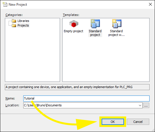
Start CODESYS and create a new project.
-
Select Standard project from the Templates list and choose a name for the project (e.g. Tutorial). Click on OK.
-
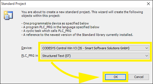
On the Standard Project window select the Device CODESYS Control Win V3 (3S - Smart Software Solutions GmbH) and Structured Text (ST) for the PLC_PRG. Click on OK.
-
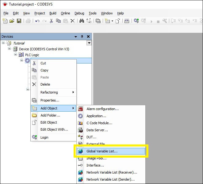
Right-click on Application and select Add Object > Global variable List.... Type FIO as the list name, click on Add.
-
Open the FIO list by Double Left-clicking on it and copy and paste the following global variables. These variables will be used to exchange data between Factory I/O and CODESYS through Modbus TCP (these are the I/O points).
VAR_GLOBAL
    iAtEntry        : BOOL;
    iLowBox         : BOOL;
    iHighBox        : BOOL;
    iAtTurnEntry    : BOOL;
    iAtLoadPos      : BOOL;
    iAtUnloadPos    : BOOL;
    iAtFront        : BOOL;
    iAtRightEntry   : BOOL;
    iAtLeftEntry    : BOOL;
    iAtRightExit    : BOOL;
    iAtLeftExit     : BOOL;

    oFeederConveyor : BOOL;
    oEntryConveyor  : BOOL;
    oLoad           : BOOL;
    oUnload         : BOOL;
    oTurn           : BOOL;
    oLeftConveyor   : BOOL;
    oRightConveyor  : BOOL;
END_VAR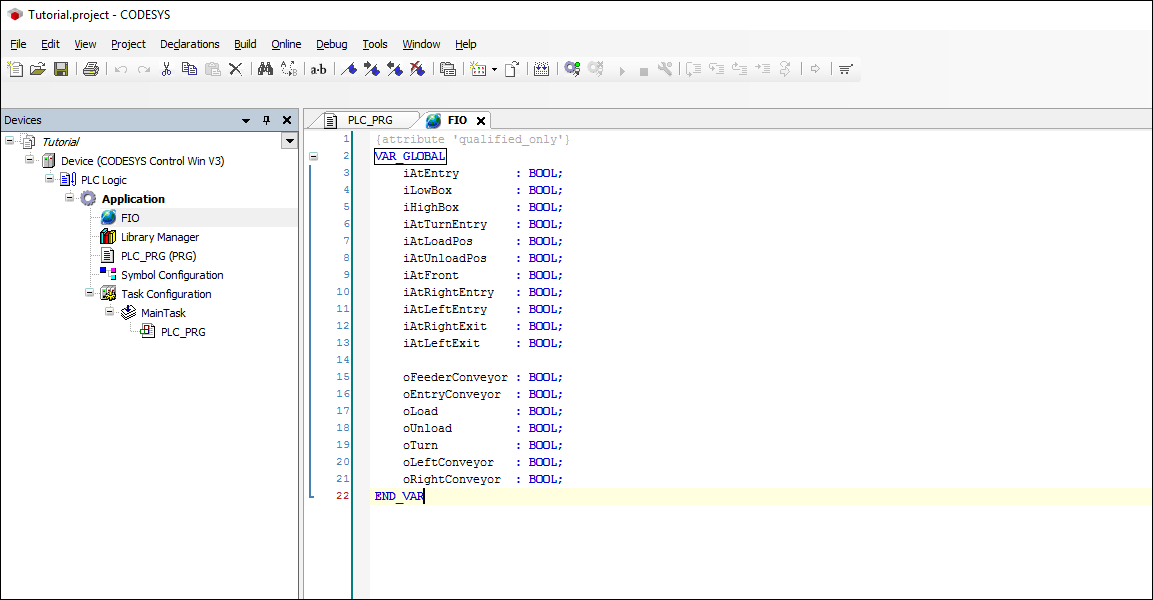
-
In the Device tree Double Left-click on PLC_PRG (PRG) and copy and paste the following variables. These are the variables you will be using in your program.
PROGRAM PLC_PRG
VAR
    F_AtEntry           : F_TRIG;
    F_AtTurnEntry       : F_TRIG;
    F_AtRightEntry      : F_TRIG;
    F_AtLeftEntry       : F_TRIG;
    F_AtRightExit       : F_TRIG;
    F_AtLeftExit        : F_TRIG;

    Pallet_on_left      : BOOL := FALSE;
    Pallet_on_right     : BOOL := FALSE;
    Idle                : BOOL := TRUE;
    Charging            : BOOL := FALSE;
    Turns_charged       : BOOL := FALSE;
    Discharging         : BOOL := FALSE;
    Turns_Discharged    : BOOL := FALSE;
    Turntable_busy      : BOOL := FALSE;
    Discharge_direction : BOOL := FALSE;
    Entry_busy          : BOOL := FALSE;
    Pallet_on_entry     : BOOL := FALSE;
    Count               : WORD := 16#8000;
END_VAR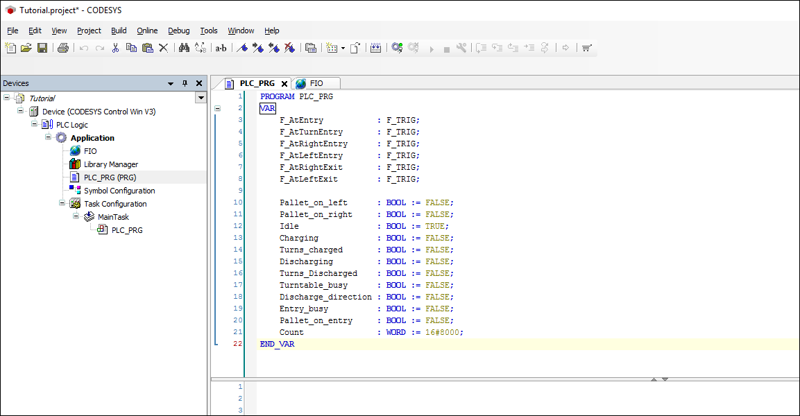
-
Now, copy and paste the following code. This is the program that will control the Sorting by Height (Advanced) scene.
F_AtEntry(CLK := FIO.iAtEntry);
F_AtTurnEntry(CLK := FIO.iAtTurnEntry);
F_AtRightEntry(CLK := FIO.iAtRightEntry);
F_AtLeftEntry(CLK := FIO.iAtLeftEntry);     (* A pallet abandons the turntable, being charged onto the left exit conveyer *)
F_AtRightExit(CLK := FIO.iAtRightExit);
F_AtLeftExit(CLK := FIO.iAtLeftExit);       (* A pallet abandons the left exit conveyer *)

(**** LEFT EXIT CONVEYER CONTROL ****)
(* Pallet_on_left represents the state of the left exit conveyer: if it carries a pallet, then Pallet_on_left = TRUE *)

IF F_AtLeftExit.Q THEN                      (* When a pallet abandons the conveyer *)
    Pallet_on_left := FALSE;                (* Reset Pallet_on_left *)
END_IF;

IF FIO.iAtLeftEntry THEN                    (* When there’s a pallet at the entry of the conveyer *)
    Pallet_on_left := TRUE;                 (* Set Pallet_on_left *)
END_IF;

FIO.oLeftConveyor := Pallet_on_left;        (* Left exit conveyer runs for Pallet_on_left = TRUE *)

(**** RIGHT EXIT CONVEYER CONTROL ****)

IF F_AtRightExit.Q THEN
    Pallet_on_right := FALSE;
END_IF;

IF FIO.iAtRightEntry THEN
    Pallet_on_right := TRUE;
END_IF;

FIO.oRightConveyor := Pallet_on_right;

(**** TURNTABLE CONTROL ****)

IF Idle AND FIO.iAtTurnEntry THEN
    Idle := FALSE;
    Charging := TRUE;
END_IF;

IF Charging AND FIO.iAtFront THEN
    Charging := FALSE;
    Turns_charged := TRUE;
END_IF;

IF Turns_charged AND FIO.iAtUnloadPos THEN
    Turns_charged := FALSE;
    Discharging := TRUE;
END_IF;

(* The turntable discharges now onto both conveyers. Thus: *)

IF Discharging AND (F_AtRightEntry.Q OR F_AtLeftEntry.Q) THEN
    Discharging := FALSE;
    Turns_Discharged := TRUE;
END_IF;

IF Turns_Discharged AND FIO.iAtLoadPos THEN
    Turns_Discharged := FALSE;
    Idle := TRUE;
END_IF;

IF F_AtTurnEntry.Q THEN
    Turntable_busy := TRUE;
END_IF;

IF Idle THEN
    Turntable_busy := FALSE;
END_IF;

(* Computing control outputs according to the current state of the turntable and the direction of the discharge *)
FIO.oLoad := Charging OR Discharging AND Discharge_direction;

(* oUnload is TRUE if the discharge is onto the left conveyer *)
FIO.oUnload := Discharging AND NOT Discharge_direction;

(* oTurn is TRUE if the discharge is onto the right conveyer *)
FIO.oTurn := Turns_charged OR Discharging;

(**** ENTRY CONVEYER CONTROL ****)
IF F_AtEntry.Q THEN
    Count := ROL (Count,1);
    IF (Count = WORD#16#2) THEN
        Entry_busy := TRUE;
    END_IF;
END_IF;

IF F_AtTurnEntry.Q THEN
    (** Defining the direction of the discharge: the direction of the discharge changes every time a pallet is
    discharged from the entry conveyer onto the turntable. If Discharge_direction = FALSE, then the discharge is onto the right conveyer **)
    Discharge_direction := NOT Discharge_direction;

    Entry_busy := FALSE;
    Count := ROR(Count,1);

    IF (Count = WORD#16#8000) THEN
        Pallet_on_entry := FALSE;
    END_IF;
END_IF;

IF FIO.iAtEntry THEN
    Pallet_on_entry := TRUE;
END_IF;

FIO.oEntryConveyor := Pallet_on_entry AND (NOT Turntable_busy OR NOT FIO.iAtTurnEntry);

(**** FEEDING CONVEYER CONTROL ****)
FIO.oFeederConveyor := NOT Entry_busy OR NOT FIO.iAtEntry;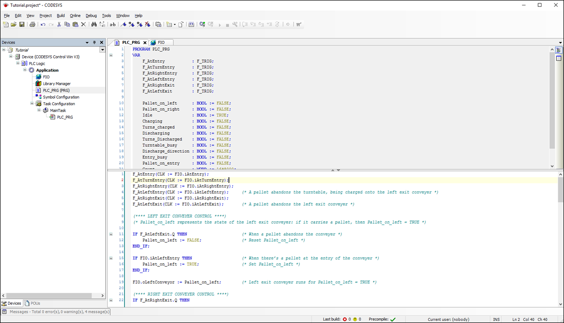
-
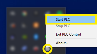
Right-click on CODESYS Control Win PLC icon (Systray) and select Start PLC.
-
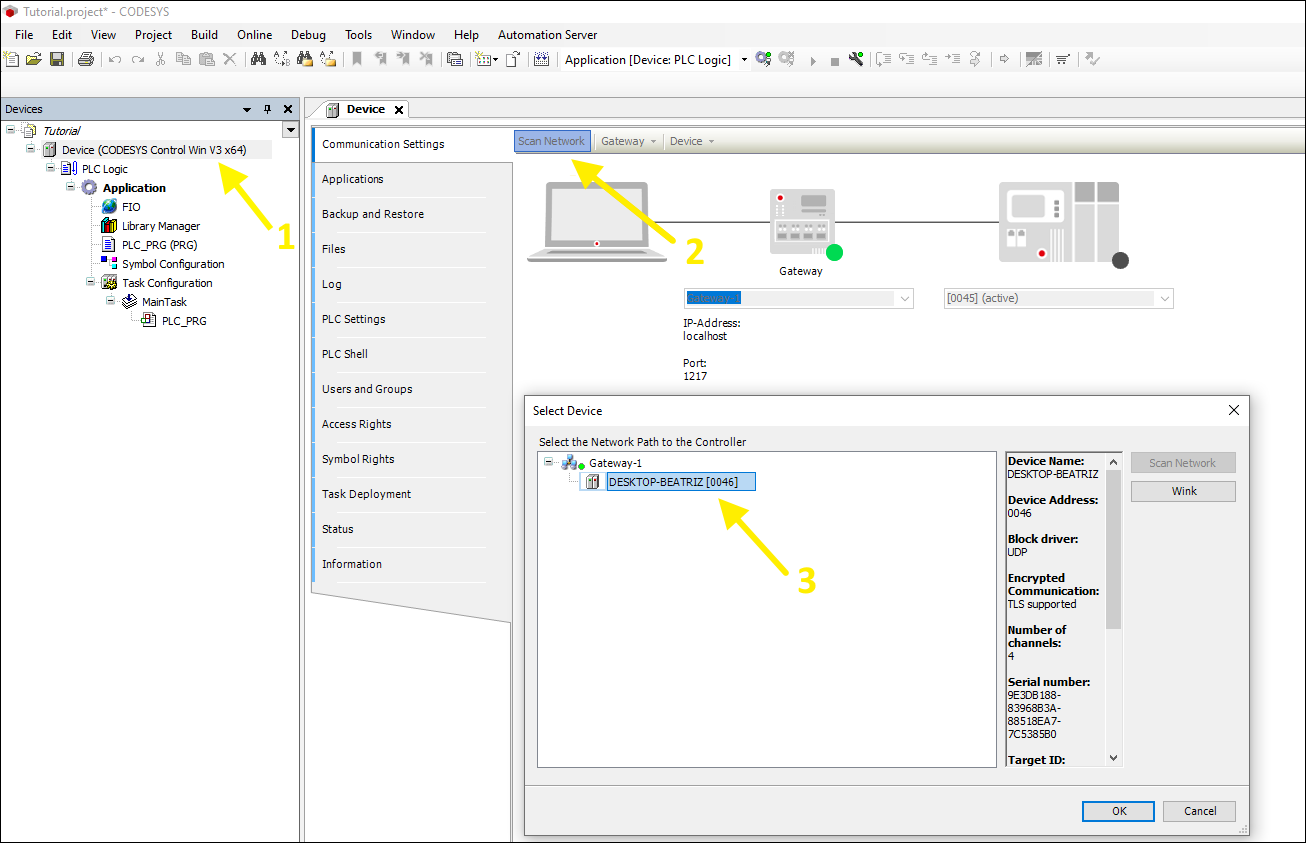
Get back to CODESYS and in the project tree, Double Left-click on Device (CODESYS Control Win V3) and then on Communication Settings. Now, click on Scan network... and select the network path to the controller. Click on OK.
-
In the toolbar click on Build > Build (F11).
-
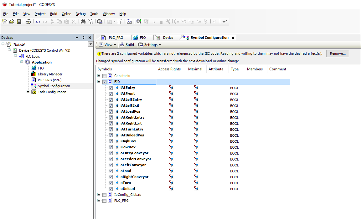
Now, Right-click on Application and select Add Object > Symbol Configuration. Next click on Add. Now, check the FIO symbols and click on Build.
-
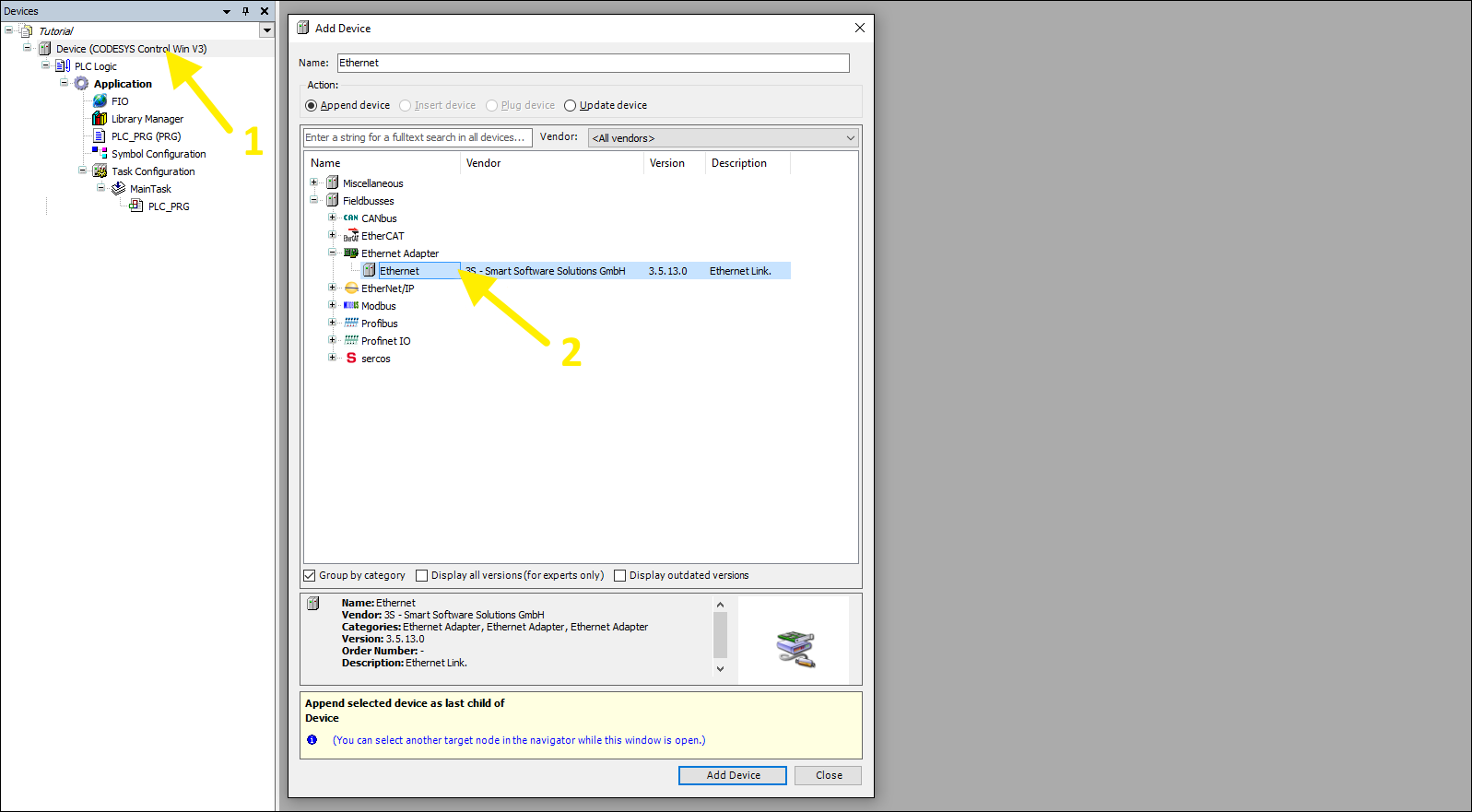
Right-click on Device (CODESYS Control Win V3) (1) and select Add Device... Next, expand Fieldbuses > Ethernet Adapter and click on Ethernet (2). Click on Add Device.
-
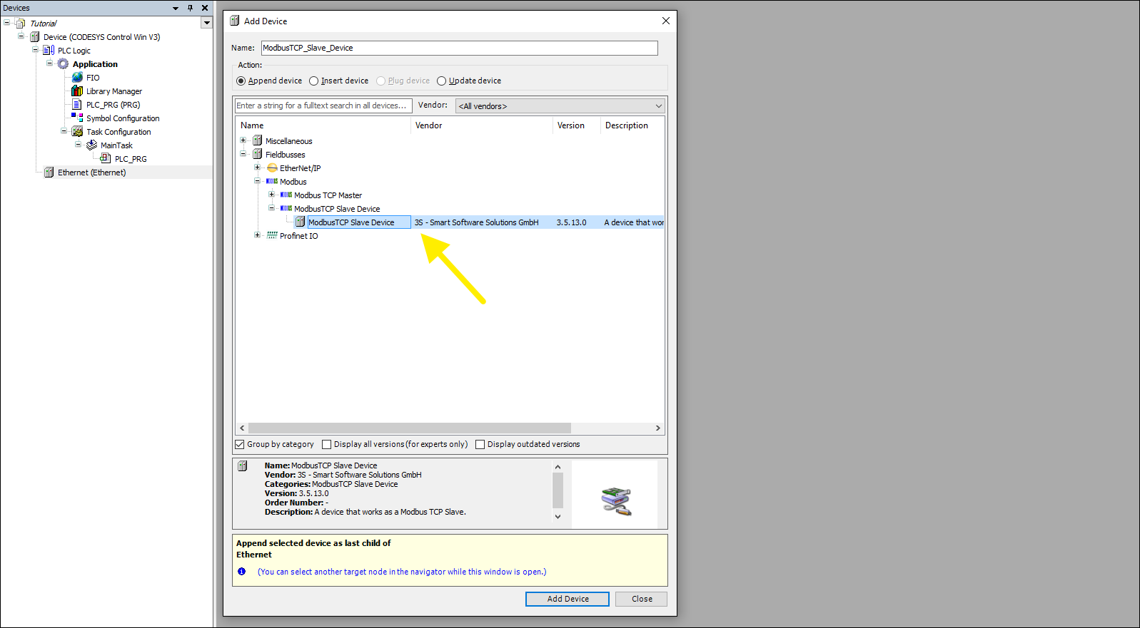
Right-click on Ethernet and select Add Device.., expand Fieldbuses > Modbus > Modbus TCP Slave Device and select Modbus TCP Slave Device. Next, click on Add Device.
-
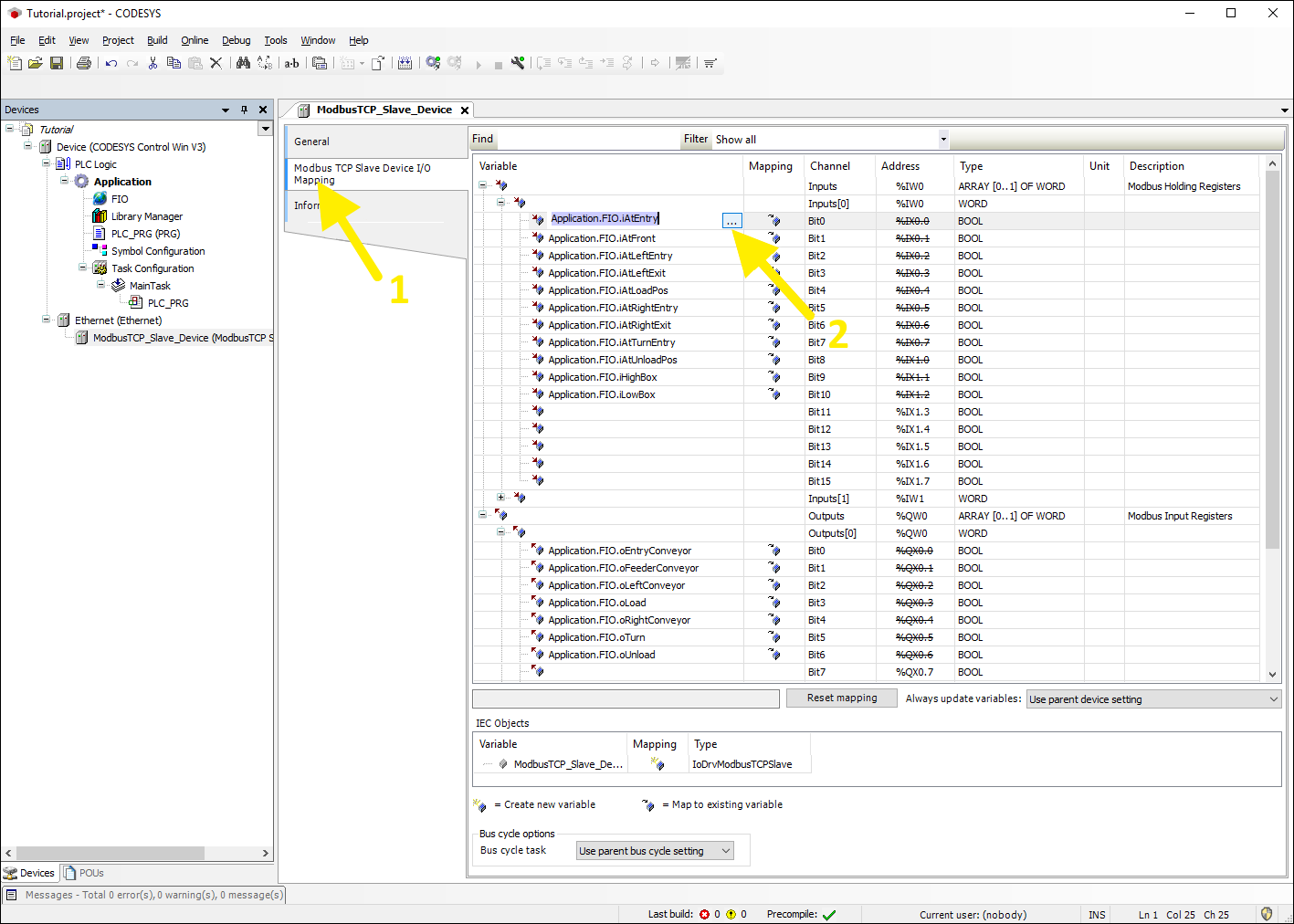
Double-click on Modbus TCP Slave Device (added in the previous step) and open Modbus TCP Slave Device I/O Mapping (1). Now, map the global variables (2) defined in step 5 as shown in the image below.
-
Next, click on Online > Login (Alt+F8). When prompted to download the program to the PLC, click on Yes.
-
Finally, click on Debug > Start (F5).
Setting up Factory I/O
-
Open any scene in Factory I/O and click on File > Driver Configuration.
-
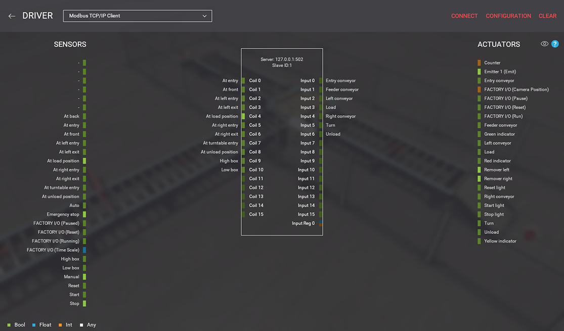
Select Modbus TCP/IP Client from the Driver list and click on CONFIGURATION. Next, set Register Inputs and Register Outputs to 0, since we are not using any in this tutorial.
-
Map the sensors and actuators tags as shown in the image below.
-
Finally, click on CONNECT, close the Driver window and start the simulation (press F5).