Sensors
Sensors are used to detect the presence of parts, measure distances and even determine the type of a part.
Fine Rotation
All sensors include a gizmo which can be used to rotate around the local up axis (Left-click and drag). Alternatively, you can rotate a sensor or reset the rotation through the Context Menu.
Range
Sensor range can be manually set by Left-clicking and dragging the white circle gizmo (Capacitive, Inductive, Diffuse and Retroreflective sensors as well as RFID reader).
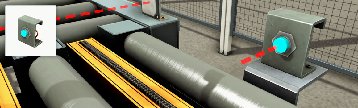
Capacitive Sensor
Proximity sensor used for close detection of any material. It is equipped with an LED, which indicates the presence of an object within its range. The output value can be digital or analog according to the selected configuration.
- LED: green (detecting)
- Detectable materials: solids and liquids.
- Sensing range: 0 - 0.2 m
Configurations
Digital
| Tag | Controller I/O | Type | Description |
|---|---|---|---|
| Capacitive Sensor # | Input | Bool | Detecting. |
Analog
| Tag | Controller I/O | Type | Description |
|---|---|---|---|
| Capacitive Sensor # (V) | Input | Float | [0, 10] V: distance between sensor and detected object. |
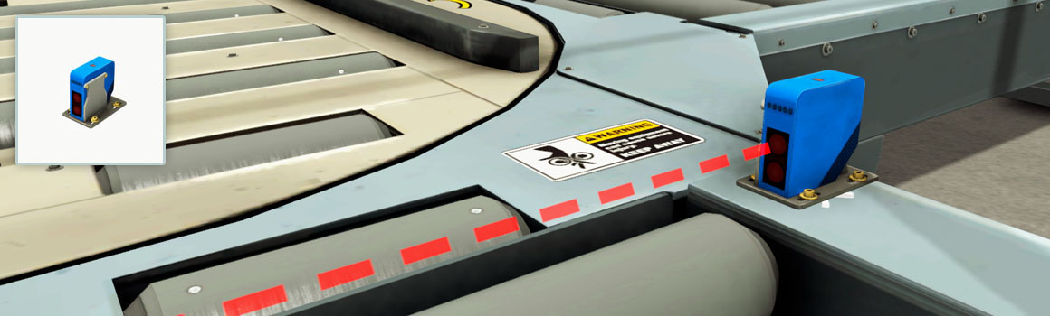
Diffuse sensor
Diffuse photoelectric sensor which can detect any solid object.
- LED: red (detecting)
- Detectable materials: solids
- Sensing range: 0 - 1.6 m
| Tag | Controller I/O | Type | Description |
|---|---|---|---|
| Diffuse Sensor # | Input | Bool | Detecting. |
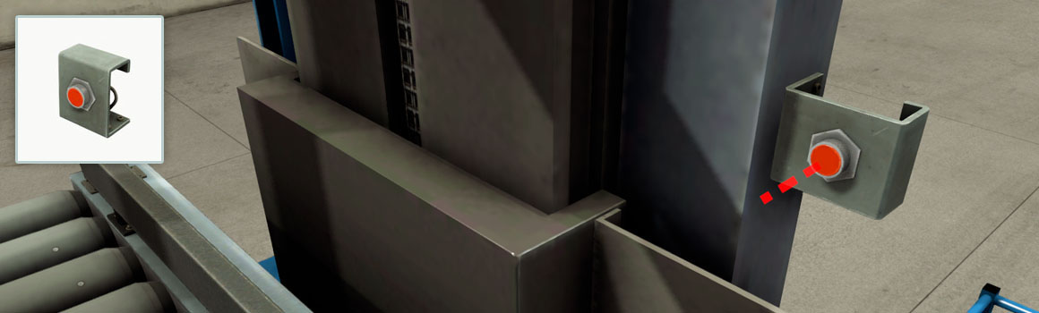
Inductive Sensor
Proximity sensor used for close detection of conductive materials. It is equipped with a LED, which indicates the presence of an object within its range. The output value can be digital or analog, according to the selected configuration.
- LED: red (detecting)
- Detectable materials: conductive
- Sensing range: 0 - 0.1 m
Configurations
Digital
| Tag | Controller I/O | Type | Description |
|---|---|---|---|
| Inductive Sensor # | Input | Bool | Detecting. |
Analog
| Tag | Controller I/O | Type | Description |
|---|---|---|---|
| Inductive Sensor # (V) | Input | Float | [0, 10] V: distance between sensor and detected object. |
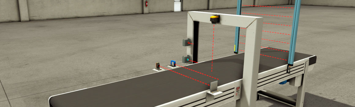
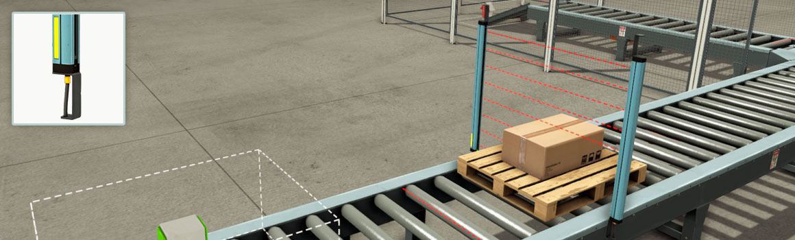
Light Array (Emitter and Receiver)
A set of parallel light beams used to create a sensing field. To ensure the synchronization of both devices (emitter and receiver), they must be properly aligned and facing each other. Once this alignment is guaranteed (indicated by a green LED), all beams can be interrupted without breaking the synchronization. Can be configured to work in Numerical, Digital or Analog mode.
- Number of beams: 8
- Range: 1.5 m
- Detectable materials: solids
- Analog value = 10 * number of interrupted beams / 8
Configurations
Numerical
| Tag | Controller I/O | Type | Description |
|---|---|---|---|
| Light Array Emitter # (Value) | Input | Integer | Each integer bit represents a beam. |
Digital
| Tag | Controller I/O | Type | Description |
|---|---|---|---|
| Light Array Emitter # (Beam 1) | Input | Bool | Detecting. |
| Light Array Emitter # (Beam 2) | Input | Bool | Detecting. |
| Light Array Emitter # (Beam 3) | Input | Bool | Detecting. |
| Light Array Emitter # (Beam 4) | Input | Bool | Detecting. |
| Light Array Emitter # (Beam 5) | Input | Bool | Detecting. |
| Light Array Emitter # (Beam 6) | Input | Bool | Detecting. |
| Light Array Emitter # (Beam 7) | Input | Bool | Detecting. |
| Light Array Emitter # (Beam 8) | Input | Bool | Detecting. |
Analog
| Tag | Controller I/O | Type | Description |
|---|---|---|---|
| Light Array Emitter # (V) | Input | Float | Light Array # (V) |
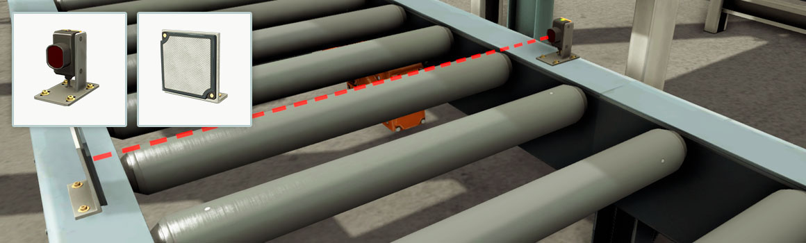
Retroreflective Sensor and Reflector
Unlike the other sensors, the retroreflective sensor requires a reflector. To work properly, it must be aligned with the reflector. It is equipped with two LEDs which indicate the correct alignment (green) and detection status (yellow).
- Green LED: aligned with the reflector
- Yellow LED: light beam not interrupted
- Detectable materials: solids
- Sensing range: 0 - 6 m
| Tag | Controller I/O | Type | Description |
|---|---|---|---|
| Retroreflective Sensor # | Input | Bool | Light beam interrupted. |
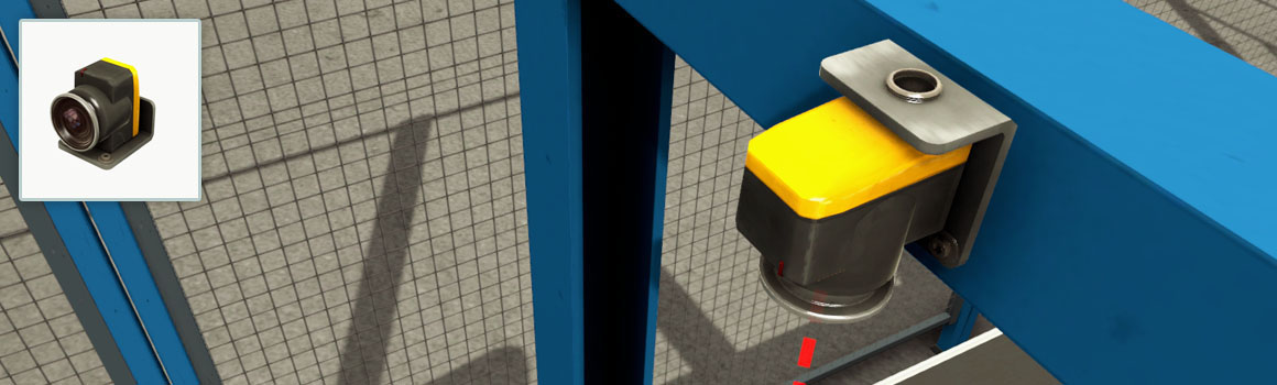
Vision Sensor
The Vision Sensor recognizes Raw Materials, Product Lids and Product Bases, and their respective colors.
- LED: red (detecting)
- Detectable materials: Raw Materials, Product Bases, Product Lids
- Sensing range: 0.3 - 2 m
This sensor can be configured to detect more than one part type by selecting the proper configuration:
- All Digital: return four digital inputs indicating which item was detected
- All Numerical: return a value that encodes the detected item
- All ID: returns a unique (random) value that identifies the detected item. Can be used similarly to barcode or RFID readers.
Items Encoding Per Configuration
| Item | All Digital | All Numerical | All ID |
|---|---|---|---|
| Bit 0 1 2 3 | Value | Value | |
| None | 0 0 0 0 | 0 | 0 |
| Blue Raw Material | 1 0 0 0 | 1 | ID |
| Blue Product Lid | 0 1 0 0 | 2 | ID |
| Blue Product Base | 1 1 0 0 | 3 | ID |
| Green Raw Material | 0 0 1 0 | 4 | ID |
| Green Product Lid | 1 0 1 0 | 5 | ID |
| Green Product Base | 0 1 1 0 | 6 | ID |
| Metal Raw Material | 1 1 1 0 | 7 | ID |
| Metal Product Lid | 0 0 0 1 | 8 | ID |
| Metal Product Base | 1 0 0 1 | 9 | ID |
Configurations
Blue/Green/Metal Base
| Tag | Controller I/O | Type | Description |
|---|---|---|---|
| Vision Sensor # | Input | Bool | Detecting. |
Blue/Green/Metal Lid
| Tag | Controller I/O | Type | Description |
|---|---|---|---|
| Vision Sensor # | Input | Bool | Detecting. |
Blue/Green/Metal Raw
| Tag | Controller I/O | Type | Description |
|---|---|---|---|
| Vision Sensor # | Input | Bool | Detecting. |
All Digital
| Tag | Controller I/O | Type | Description |
|---|---|---|---|
| Vision Sensor # (Bit0) | Input | Bool | Item encoding bit. |
| Vision Sensor # (Bit1) | Input | Bool | Item encoding bit. |
| Vision Sensor # (Bit2) | Input | Bool | Item encoding bit. |
| Vision Sensor # (Bit3) | Input | Bool | Item encoding bit. |
All Numerical
| Tag | Controller I/O | Type | Description |
|---|---|---|---|
| Vision Sensor # (Value) | Input | Int | Value representing the detected item. |
All ID
| Tag | Controller I/O | Type | Description |
|---|---|---|---|
| Vision Sensor # (Value) | Input | Int | Unique integer (ID) that identifies an item, always positive. Note that item IDs are not persistent between scene reset and load. |
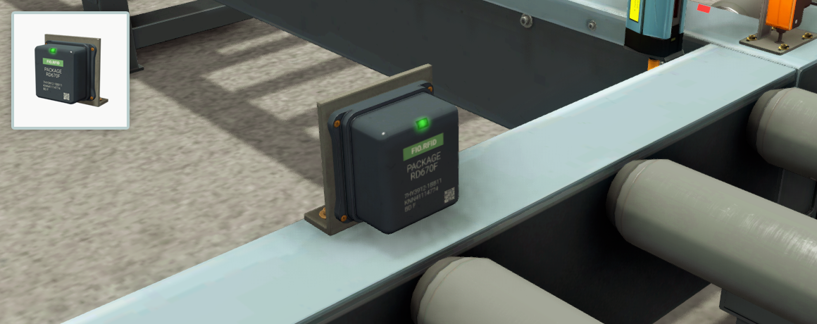
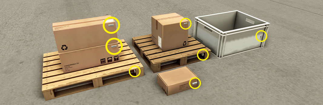
RFID Reader
RFID Tags
Note that, RFID tags should not be confused with tags of parts.
The RFID reader can be used to read/write data of RFID tags. It implements a single trigger communication design where the controller sends a command to the reader and receives a response. Almost all items include an active tag, except for raw materials, product lids and bases. RFID tags are detected within a range of 0.5m when in front of the reader. The RFID reader can only detect one tag. If more than one tag is found, an error 2 is indicated in the RFID Reader # Status tag - see a list of all status values in the table below.
Operation
Use the RFID Reader # Command to set the command to execute. Next, use RFID Reader # Execute Command to execute the current command. Check the reader status with the tag RFID Reader # Status. A status of 0 indicates success when executing a command, a value greater than 0 indicates an error - see table below. Every time a command is executed, with or without errors, the RFID Reader # Command ID is increased by one. You may use this tag to detect when a command has finished executing.
- Green LED: Idle
- Orange LED: Executing command
- Red LED: Error
RFID Tags
A RFID tag includes 128 DWORD of free memory and a unique serial number. Each DWORD can be accessed by setting the corresponding memory index (zero-based) in the reader (see table below).
| Tag | Controller I/O | Type | Description |
|---|---|---|---|
| RFID Reader # Command | Output | Int | Sets the command to execute: 0 = Is tag available? 1 = Read serial number 2 = Read data 3 = Write data 4 = Clear all data |
| RFID Reader # Execute Command | Output | Bool | Executes the defined command. |
| RFID Reader # Memory Index | Output | Int | The tag memory index where to perform a read/write operation (zero-based index). |
| RFID Reader # Write Data | Output | Int | The data to write into the tag defined by RFID Reader # Memory Index. |
| RFID Reader # Command ID | Input | Int | The number of executed commands. Can be used to detect if the current command has been already executed. |
| RFID Reader # Status | Input | Int | Status of the reader after executing a command: 0 = Success 1 = ErrorNoTag 2 = ErrorTooManyTags 3 = ErrorInvalidIndex 4 = InvalidCommand |
| RFID Reader # Read Data | Input | Int | Data read from a tag. |
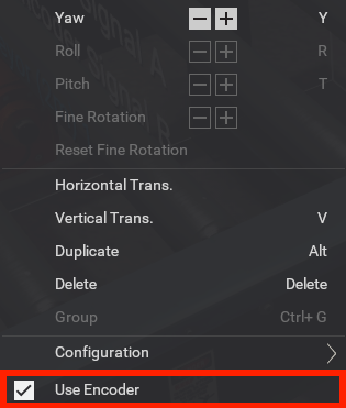
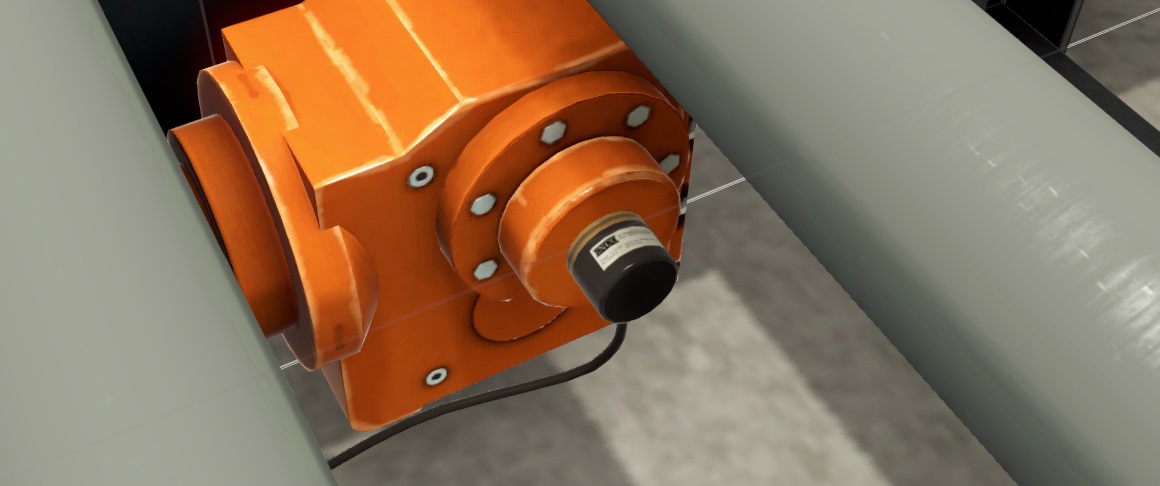
Incremental Encoder
Several parts include an incremental encoder which you can enable by right-clicking on the part and choosing Use Encoder on the Context Menu. This encoder uses two bits (A and B) to produce two wave forms which are 90 degrees out of phase (in quadrature). The encoder resolution is 0.0225 m, which is based on a velocity of 0.45 m/s at 20Hz (roller conveyor default velocity). The frequency of 20Hz has been chosen since it's easily supported by most I/O drivers.
List of parts including an encoder:
- Loading Conveyor
- Roller Conveyor (2/4/6 m)
- Curved Roller Conveyor
- Belt Conveyor (2/4/6 m)
- Curved Belt Conveyor
- Inclined Belt Conveyor
Example of rotation pulses of a roller conveyor in digital configuration.
| Phase | A | B |
|---|---|---|
| 1 | 0 | 0 |
| 2 | 0 | 1 |
| 3 | 1 | 1 |
| 4 | 1 | 0 |