Stations
Machining Center
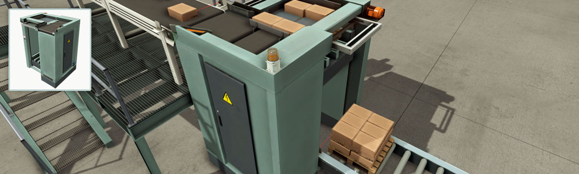
The Machining Center is a station used to manufacture lids and bases from raw materials. First, the articulated robot waits for raw material to be placed at the entry bay. When new material is detected it is loaded into the CNC machine, which will start manufacturing an item. Each item type takes a different interval of time to be produced (lids: 6 seconds; bases: 3 seconds). Once the operation is complete, the robot places the item on the exit bay.
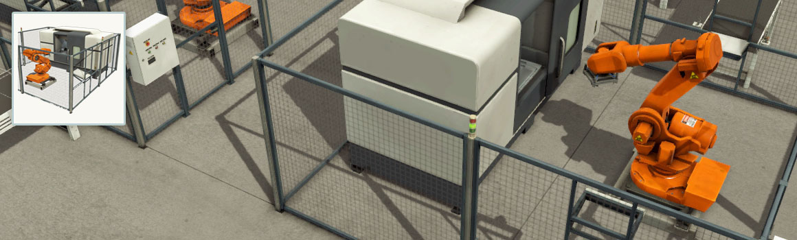
The production operation can be stopped at any time, restarted or reset. You can interact with the Machining Center through the electric switchboard next to the safeguard door:
-
Emergency: triggers an emergency stop, interrupting the articulated robot and the CNC. After an emergency stop the station can only be reset by disarming the emergency button and pressing the Reset button.
-
Start: starts the station.
-
Stop: stops the articulated robot and the CNC. To restart press the Start or Reset button.
-
Reset: resets the station.
Two stack lights placed on top of the safeguard provide information about the current status.
- Green light: not busy.
- Yellow light: busy.
- Red light: has an error (incorrect item detected at entry bay).
| Tag | Controller I/O | Type | Description |
|---|---|---|---|
| Machining Center # (Produce Lids) | Output | Bool | Set True to produce lids; False to produce bases. |
| Machining Center # (Start) | Output | Bool | Start. |
| Machining Center # (Stop) | Output | Bool | Stop. |
| Machining Center # (Reset) | Output | Bool | Reset. |
| Machining Center # (Is Busy) | Input | Bool | Indicates whether an item is being processed. |
| Machining Center # (Has Error) | Input | Bool | Indicates whether an invalid item was detected on the entry bay. |
| Machining Center # (Opened) | Input | Bool | True when the door is open. |
| Machining Center # (Progress) | Input | Float | Machining progress (0-100). |
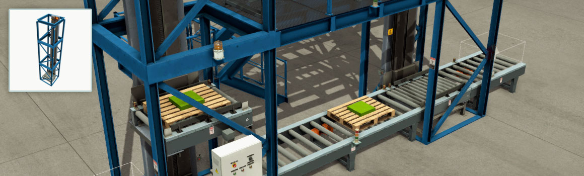
Elevator
Heavy-duty chain-driven elevator, used for transportation of all sorts of cargo between floors. The elevator is equipped with two retroreflective sensors, placed at each end of the platform. The elevator can be controlled by digital or analog values, according to the selected configuration.
- Roll radius: 45 mm
- Platform stroke: 7 m
- Platform speed: 0.68 m/s
- Maximum conveying speed: 0.45 m/s (digital); 0.8 m/s (analog)
- Retroreflective sensor LED: green (detecting reflector), yellow (beam not interrupted)
Configurations
Digital
| Tag | Controller I/O | Type | Description |
|---|---|---|---|
| Elevator # (Up) | Output | Bool | Move platform up. |
| Elevator # (Down) | Output | Bool | Move platform down. |
| Elevator # (Slow) | Output | Bool | Slow movement (20% of default speed). |
| Elevator # (+) | Output | Bool | Roll (arrow direction). |
| Elevator # (-) | Output | Bool | Roll. |
| Elevator # (Left Limit) | Input | Bool | Item detected. |
| Elevator # (Right Limit) | Input | Bool | Item detected. |
Analog
| Tag | Controller I/O | Type | Description |
|---|---|---|---|
| Elevator # Set Point (V) | Output | Float | [0, 10] V: set target position. |
| Elevator # Position (V) | Input | Float | [0, 10] V: current position. |
| Elevator # (+) | Output | Bool | Roll (arrow direction). |
| Elevator # (-) | Output | Bool | Roll. |
| Elevator # (Left Limit) | Input | Bool | Item detected. |
| Elevator # (Right Limit) | Input | Bool | Item detected. |
Pick & Place
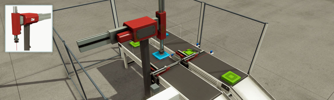
Gantry Pick and Place station with three axes controlled by servomotors. Often used to move light load cargo (e.g. cardboard boxes) into other conveyors or pallets.
The Pick and Place has four degrees of freedom, three correspond to the axes linear movement and another to gripper rotation. The gripper is enabled by suction cups and includes a proximity sensor. Can be controlled by digital and analog values, according to the selected configuration. When controlled with digital I/O, axis movement is performed incrementally (step by step) on each rising edge of the controlling tag value.
- Y-axis stroke: 1.25 m
- X-axis stroke: 2.125 m
- Z-axis stroke: 0.5m
- Step: 0.125 m
- Beam speed: 1.5 m/s
- Gripper angular speed: 4.6 rad/s
Configurations
Digital
| Tag | Controller I/O | Type | Description |
|---|---|---|---|
| Pick & Place # X(+) | Output | Bool | Take a positive step along X-axis. |
| Pick & Place # X(-) | Output | Bool | Take a negative step along X-axis. |
| Pick & Place # Y(+) | Output | Bool | Take a positive step along Y-axis. |
| Pick & Place # Y(-) | Output | Bool | Take a negative step along Y-axis. |
| Pick & Place # Z(+) | Output | Bool | Take a positive step along Z-axis. |
| Pick & Place # Z(-) | Output | Bool | Take a negative step along Z-axis. |
| Pick & Place # C(+) | Output | Bool | Rotate gripper. |
| Pick & Place # (Grab) | Output | Bool | Activate suction cups. |
| Pick & Place # (Moving-Z) | Input | Bool | Moving along Z-axis. |
| Pick & Place # (Moving-XY) | Input | Bool | Moving along XY-plane. |
| Pick & Place # (Box Detected) | Input | Bool | Detecting an item. |
| Pick & Place # (C Limit) | Input | Bool | Gripper at angular limit. |
Analog
| Tag | Controller I/O | Type | Description |
|---|---|---|---|
| Pick & Place # X Set Point (V) | Output | Float | [0, 10] V: set target position along X-axis. |
| Pick & Place # Y Set Point (V) | Output | Float | [0, 10] V: set target position along Y-axis. |
| Pick & Place # Z Set Point (V) | Output | Float | [0, 10] V: set target position along Z-axis. |
| Pick & Place # C(+) | Output | Bool | Rotate gripper. |
| Pick & Place # (Grab) | Output | Bool | Activate suction cups. |
| Pick & Place # X Position (V) | Input | Float | [0, 10] V: current position along X-axis. |
| Pick & Place # Y Position (V) | Input | Float | [0, 10] V: cuurrent position along Y-axis. |
| Pick & Place # Z Position (V) | Input | Float | [0, 10] V: current position along Z-axis. |
| Pick & Place # (Box Detected) | Input | Bool | Detecting an item. |
| Pick & Place # (C Limit) | Input | Bool | Gripper at angular limit. |
Digital & Analog
| Tag | Controller I/O | Type | Description |
|---|---|---|---|
| Pick & Place # X Set Point (V) | Output | Float | [0, 10] V: set target position along X-axis. |
| Pick & Place # Y Set Point (V) | Output | Float | [0, 10] V: set target position along Y-axis. |
| Pick & Place # Z Set Point (V) | Output | Float | [0, 10] V: set target position along Z-axis. |
| Pick & Place # C(+) | Output | Bool | Rotate gripper. |
| Pick & Place # (Grab) | Output | Bool | Activate suction cups. |
| Pick & Place # X Position (V) | Input | Float | [0, 10] V: current position along X-axis. |
| Pick & Place # Y Position (V) | Input | Float | [0, 10] V: current position along Y-axis. |
| Pick & Place # Z Position (V) | Input | Float | [0, 10] V: current position along Z-axis. |
| Pick & Place # (Moving-Z) | Input | Bool | Moving along Z-axis. |
| Pick & Place # (Moving-XY) | Input | Bool | Moving along XY-plane. |
| Pick & Place # (Box Detected) | Input | Bool | Detecting an item. |
| Pick & Place # (C Limit) | Input | Bool | Gripper at angular limit. |
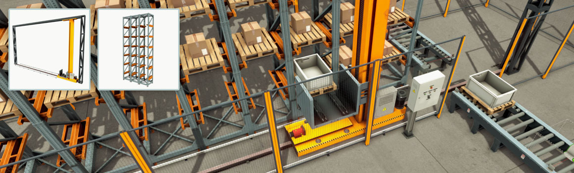
Stacker Crane and Rack
Rail-mounted stacker crane used to stock heavy cargo. Includes a cart, a vertical platform, and two forks which may slide to both sides.
Two laser rangefinders, placed on the cart and the platform, measure the horizontal and vertical position of the platform. Racks are upright steel frames connected by horizontal steel beams with the purpose to store loads. The available rack is a single-deep rack type, also known as selective rack, which only allows loads to be stored one pallet deep. Loads can be stored from both sides of the rack.
Each rack must be aligned with one of the rail ends, making the stacker crane stop at the correct position. The stacker crane can be controlled by Digital, Numerical and Analog values, according to the selected configuration.
- Forks stroke: 1.2 m
- Cart stroke: 10.5 m
- Platform stroke: 6.625 m
- Cart speed: 1.4 m/s
- Forks speed: 0.5 m/s
- Platform speed: 1.7 m/s
- Number of cells: 18
-
Numerical: the target cell can be defined by an integer value between 1 and 54. If this value is set to zero, the stacker crane stops at the current position. However, if it is higher than 54, it will move to the rest position (55).
-
Analog: the target/current position for each axis can be set/measured with analog values.
-
Digital: each cell number is encoded by five digital values (see the following table)
| Position | Actuators |
|---|---|
| Bit 0 1 2 3 4 5 | |
| Locked | 000000 |
| 1 | 100000 |
| 2 | 010000 |
| 3 | 001000 |
| ... | ... |
| 55 (rest) | 111011 |
Configurations
Numerical
| Tag | Controller I/O | Type | Description |
|---|---|---|---|
| Stacker Crane # Target Position | Output | Integer | Move to the desired cell. |
| Stacker Crane # (Left) | Output | Bool | Move forks left. |
| Stacker Crane # (Right) | Output | Bool | Move forks right. |
| Stacker Crane # Lift | Output | Bool | Slightly raises the platform for loading/unloading operations. |
| Stacker Crane # Moving-X | Input | Bool | Moving along X-axis. |
| Stacker Crane # Moving-Z | Input | Bool | Moving along Z-axis. |
| Stacker Crane # Left Limit | Input | Bool | Forks at left limit. |
| Stacker Crane # Middle Limit | Input | Bool | Forks at middle. |
| Stacker Crane # Right Limit | Input | Bool | Forks at right limit. |
Analog
| Tag | Controller I/O | Type | Description |
|---|---|---|---|
| Stacker Crane # X Set Point (V) | Output | Float | [0, 10] V: set target position along X-axis. |
| Stacker Crane # Z Set Point (V) | Output | Float | [0, 10] V: set target position along Z-axis. |
| Stacker Crane # (Left) | Output | Bool | Move forks left. |
| Stacker Crane # (Right) | Output | Bool | Move forks right. |
| Stacker Crane # X Position (V) | Input | Float | [0, 10] V: current position along X-axis. |
| Stacker Crane # Z Position (V) | Input | Float | [0, 10] V: current position along Z-axis. |
| Stacker Crane # Left Limit | Input | Bool | Forks at left limit. |
| Stacker Crane # Middle Limit | Input | Bool | Forks at middle. |
| Stacker Crane # Right Limit | Input | Bool | Forks at right limit. |
Digital
| Tag | Controller I/O | Type | Description |
|---|---|---|---|
| Stacker Crane # Target Position Bit0 | Output | Bool | Target position encoding bit (least significant). |
| Stacker Crane # Target Position Bit1 | Output | Bool | Target position encoding bit. |
| Stacker Crane # Target Position Bit2 | Output | Bool | Target position encoding bit. |
| Stacker Crane # Target Position Bit3 | Output | Bool | Target position encoding bit. |
| Stacker Crane # Target Position Bit4 | Output | Bool | Target position encoding bit. |
| Stacker Crane # Target Position Bit5 | Output | Bool | Target position encoding bit. |
| Stacker Crane # (Left) | Output | Bool | Move forks left. |
| Stacker Crane # (Right) | Output | Bool | Move forks right. |
| Stacker Crane # Lift | Output | Bool | Slightly raises the platform for loading/unloading operations. |
| Stacker Crane # Moving-X | Input | Bool | Moving along X-axis. |
| Stacker Crane # Moving-Z | Input | Bool | Moving along Z-axis. |
| Stacker Crane # Left Limit | Input | Bool | Forks at left limit. |
| Stacker Crane # Middle Limit | Input | Bool | Forks at middle. |
| Stacker Crane # Right Limit | Input | Bool | Forks at right limit. |
Digital & Analog
| Tag | Controller I/O | Type | Description |
|---|---|---|---|
| Stacker Crane # X Set Point (V) | Output | Float | [0, 10] V: set target position along X-axis. |
| Stacker Crane # Z Set Point (V) | Output | Float | [0, 10] V: set target position along Z-axis. |
| Stacker Crane # (Left) | Output | Bool | Move forks left. |
| Stacker Crane # (Right) | Output | Bool | Move forks right. |
| Stacker Crane # X Position (V) | Input | Float | [0, 10] V: current position along X-axis. |
| Stacker Crane # Z Position (V) | Input | Float | [0, 10] V: current position along Z-axis. |
| Stacker Crane # Moving-X | Input | Bool | Moving along X-axis. |
| Stacker Crane # Moving-Z | Input | Bool | Moving along Z-axis. |
| Stacker Crane # Left Limit | Input | Bool | Forks at left limit. |
| Stacker Crane # Middle Limit | Input | Bool | Forks at middle. |
| Stacker Crane # Right Limit | Input | Bool | Forks at right limit. |
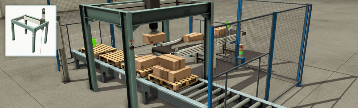
Palletizer
High-level palletizer used to stack cardboard boxes (Palletizing Box) on pallets.
- Pusher stroke: 0.88 m
- Elevator stroke: 1.75 m
- Elevator speed: 2 m/s
| Tag | Controller I/O | Type | Description |
|---|---|---|---|
| Palletizer # (Push) | Output | Bool | Move pusher. |
| Palletizer # (Turn) | Output | Bool | Turn flipper (used to rotate boxes by 90º). |
| Palletizer # (Clamp) | Output | Bool | Move clamper. |
| Palletizer # Belt (+) | Output | Bool | Rotate (input direction). |
| Palletizer # Belt (-) | Output | Bool | Rotate (output direction). |
| Palletizer # Chain (+) | Output | Bool | Rotate (input direction). |
| Palletizer # Chain (-) | Output | Bool | Rotate (output direction). |
| Palletizer # (Open Plate) | Output | Bool | Opens the plate. |
| Palletizer # Elevator + | Output | Bool | Moves the elevator up. |
| Palletizer # Elevator - | Output | Bool | Moves the elevator down. |
| Palletizer # Elevator (Move to Limit) | Output | Bool | Indicates that the elevator should move to the limit (up/down) and not by steps. |
| Palletizer # (Clamped) | Input | Bool | Clamper reached the front limit. |
| Palletizer # (Plate Limit) | Input | Bool | Plate is closed. |
| Palletizer # (Pusher Limit) | Input | Bool | Pusher is at front/back limit. |
| Palletizer # (Elevator Moving) | Input | Bool | Indicates the elevator is moving. |
| Palletizer # Elevator (Back Limit) | Input | Bool | Elevator back sensor. |
| Palletizer # Elevator (Front Limit) | Input | Bool | Elevator front sensor. |
Two-Axis Pick & Place
This part can be used to assemble Lids on Bases or pick and place items from one place to another. To guarantee a correct fit, bases and lids should be properly aligned by Positioning Bars.
- X-axis stroke: 1.125 m
- Z-axis stroke: 0.625 m
- Arm and picker speed: 2 m/s
- Z-axis rotation in 90° increments (arm and gripper)
Configurations
Digital
| Tag | Controller I/O | Type | Description |
|---|---|---|---|
| Two-Axis Pick & Place # Z | Output | Bool | Move along Z-axis. |
| Two-Axis Pick & Place # X | Output | Bool | Move along X-axis. |
| Two-Axis Pick & Place # Rotate CW | Output | Bool | Rotate clockwise. |
| Two-Axis Pick & Place # Rotate CCW | Output | Bool | Rotate counterclockwise. |
| Two-Axis Pick & Place # Gripper CW | Output | Bool | Rotate gripper clockwise. |
| Two-Axis Pick & Place # Gripper CCW | Output | Bool | Rotate gripper counterclockwise. |
| Two-Axis Pick & Place # (Grab) | Output | Bool | Activate suction cup. |
| Two-Axis Pick & Place # (Moving X) | Input | Bool | Moving along X-axis. |
| Two-Axis Pick & Place # (Moving Z) | Input | Bool | Moving along Z-axis. |
| Two-Axis Pick & Place # (Rotating) | Input | Bool | Rotating. |
| Two-Axis Pick & Place # (Gripper rotating) | Input | Bool | Gripper rotating. |
| Two-Axis Pick & Place # (Detected) | Input | Bool | Detecting an item. |
Analog
| Tag | Controller I/O | Type | Description |
|---|---|---|---|
| Two-Axis Pick & Place # X Set Point (V) | Output | Float | [0, 10] V: set target position along X-axis. |
| Two-Axis Pick & Place # Z Set Point (V) | Output | Float | [0, 10] V: set target position along Z-axis. |
| Two-Axis Pick & Place # Rotate CW | Output | Bool | Rotate clockwise. |
| Two-Axis Pick & Place # Rotate CCW | Output | Bool | Rotate counterclockwise. |
| Two-Axis Pick & Place # Gripper CW | Output | Bool | Rotate gripper clockwise. |
| Two-Axis Pick & Place # Gripper CCW | Output | Bool | Rotate gripper counterclockwise. |
| Two-Axis Pick & Place # (Grab) | Output | Bool | Activate suction cup. |
| Two-Axis Pick & Place # X Position (V) | Input | Float | [0, 10] V: current position along X-axis. |
| Two-Axis Pick & Place # Z Position (V) | Input | Float | [0, 10] V: current position along Z-axis. |
| Two-Axis Pick & Place # (Rotating) | Input | Bool | Rotating. |
| Two-Axis Pick & Place # (Gripper rotating) | Input | Bool | Gripper rotating. |
| Two-Axis Pick & Place # (Detected) | Input | Bool | Detecting an item. |
Digital & Analog
| Tag | Controller I/O | Type | Description |
|---|---|---|---|
| Two-Axis Pick & Place # X Set Point (V) | Output | Float | [0, 10] V: set target position along X-axis. |
| Two-Axis Pick & Place # Z Set Point (V) | Output | Float | [0, 10] V: set target position along Z-axis. |
| Two-Axis Pick & Place # Rotate CW | Output | Bool | Rotate clockwise. |
| Two-Axis Pick & Place # Rotate CCW | Output | Bool | Rotate counterclockwise. |
| Two-Axis Pick & Place # Gripper CW | Output | Bool | Rotate gripper clockwise. |
| Two-Axis Pick & Place # Gripper CCW | Output | Bool | Rotate gripper counterclockwise. |
| Two-Axis Pick & Place # (Grab) | Output | Bool | Activate suction cup. |
| Two-Axis Pick & Place # X Position (V) | Input | Float | [0, 10] V: current position along X-axis. |
| Two-Axis Pick & Place # Z Position (V) | Input | Float | [0, 10] V: current position along Z-axis. |
| Two-Axis Pick & Place # (Moving X) | Input | Bool | Moving along X-axis. |
| Two-Axis Pick & Place # (Moving Z) | Input | Bool | Moving along Z-axis. |
| Two-Axis Pick & Place # (Rotating) | Input | Bool | Rotating. |
| Two-Axis Pick & Place # (Gripper rotating) | Input | Bool | Gripper rotating. |
| Two-Axis Pick & Place # (Detected) | Input | Bool | Detecting an item. |
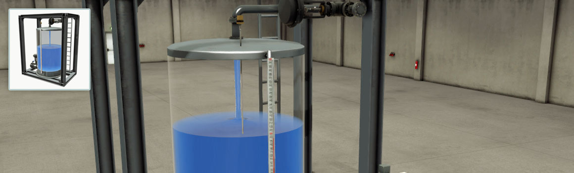
Tank
Liquid tank including two control valves and a capacitive level sensor which can be used to control the flow of liquid in and out of the tank. Control valves are controlled by pneumatic actuators that can be positioned with signals between 0 and 10 V. Note that capacitive sensors can also be used to detect liquid levels. The liquid tank is primarily intended to be used for level and flow control using a PID.
- Height: 3 m
- Diameter: 2 m
- Discharge pipe radius: 0.125 m
- Max. input flow: 0.25 m³/s
- Max. output flow: 0.3543 m³/s
- Capacitive sensors can detect liquid
Configurations
Analog
| Tag | Controller I/O | Type | Description |
|---|---|---|---|
| Tank # (Fill Valve) | Output | Float | [0, 10] V: fill valve positioning. |
| Tank # (Discharge Valve) | Output | Float | [0, 10] V: discharge valve positioning. |
| Tank # (Level Meter) | Input | Float | [0, 10] V: level meter value. |
| Tank # (Flow Meter) | Input | Float | [0, 10] V: flow meter value (10 V = 0.3543 m³/s). |
Digital
| Tag | Controller I/O | Type | Description |
|---|---|---|---|
| Tank (Fill Valve) | Output | Bool | Open fill valve. |
| Tank (Discharge Valve) | Output | Bool | Open discharge valve. |