Unity Pro Soft PLC through Modbus TCP/IP
Requirements
- Modbus & OPC Edition or Ultimate Edition
- Schneider Unity Pro
This tutorial gives you step-by-step instructions on how to use Schneider Unity Pro SoftPLC to control Factory I/O through Modbus TCP/IP. We will be using Unity Pro simulation mode, which simulates an M340 PLC with a Modbus server. Factory I/O will be running as a Modbus TCP/IP client.
Setting up Factory I/O
-
Download the zip archive (top of this page), extract it and open the project in Schneider Unity Pro.
-
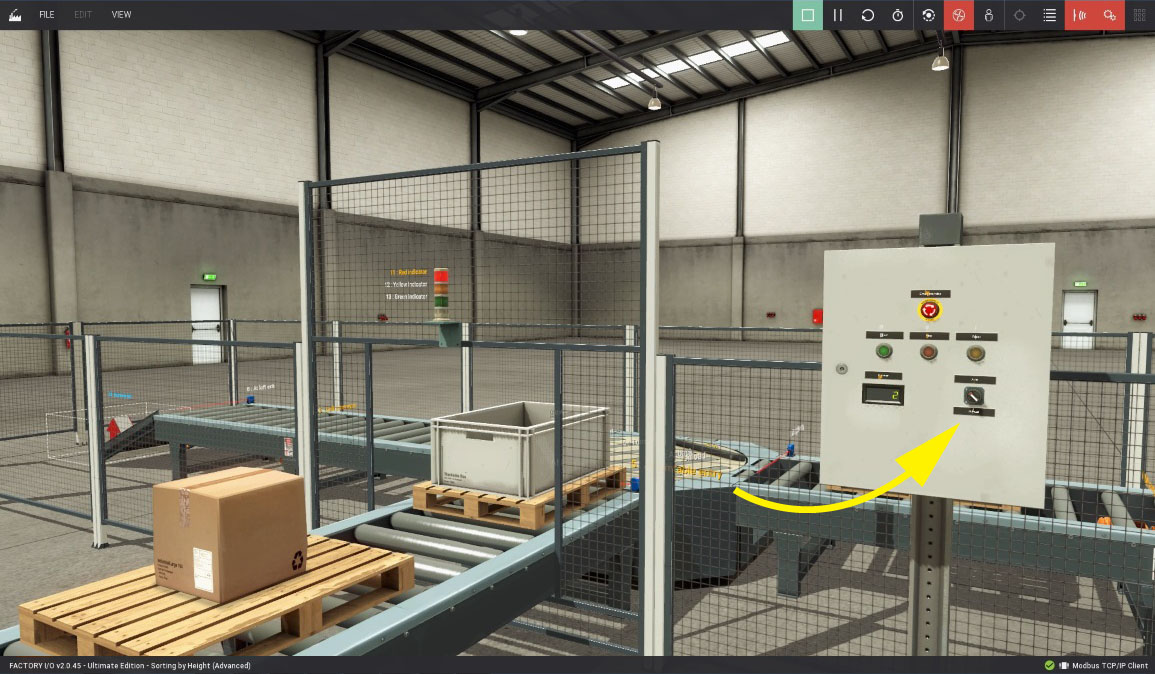
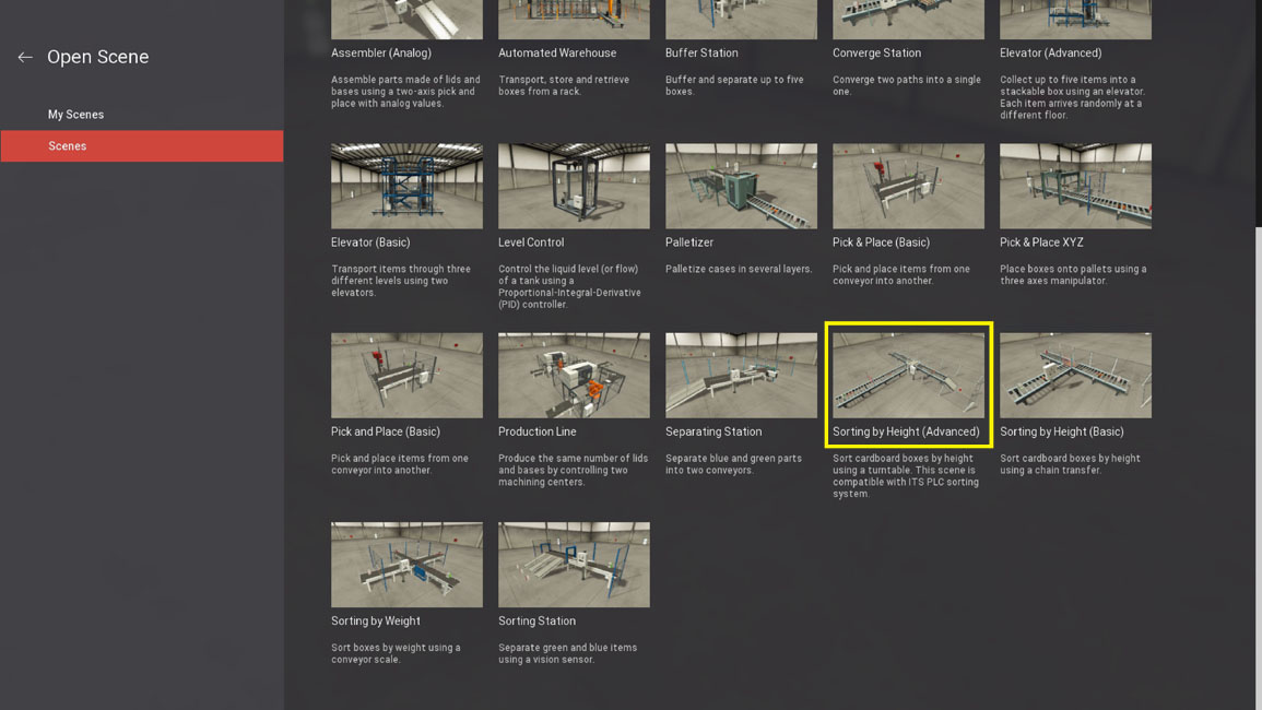
Start Factory I/O and open the Sorting by Height (Advanced) scene.
-
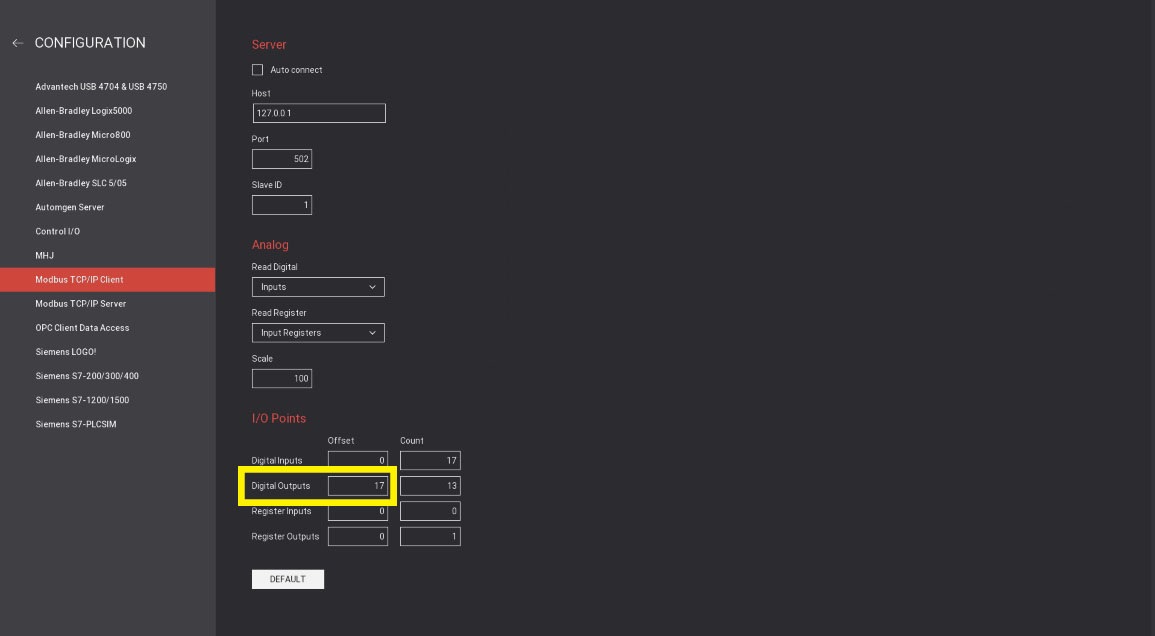
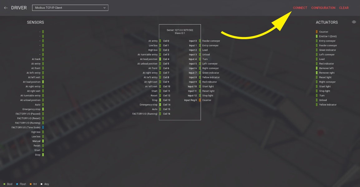
Press F4 to open the Driver Window. Note that I/O points are already setup with 17 digital inputs (sensors), 13 digital outputs (actuators) and 1 input register (number shown by the display: Counter).
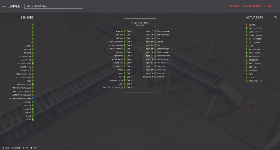
Modbus TCP/IP clients can only write to Coils. Read operations can be performed on Coils or Inputs according to settings chosen in the CONFIGURATION panel.
In Schneider Unity Pro, both Coils and Inputs are stored in internal Boolean memories (%M) and share the same memory space. We are setting an Offset of 17 to Outputs in order to have the first 17 addresses available for Coils (sensors). Also, in Schneider Unity pro, both Discrete Inputs and Holding Registers are stored in internal Word memories (%MW).
On this sample, digital input I/O points (sensors) are written to %M0 up to %M16, and digital outputs (actuators) are read from %M17 up to %M29. The discrete output point used by the display (Counter) is read from %MW0.
Setting up Unity Pro
-
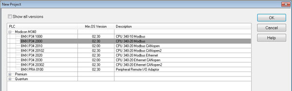
Start Unity Pro and create a new project (FILE > New). Then select a M340 PLC.
-
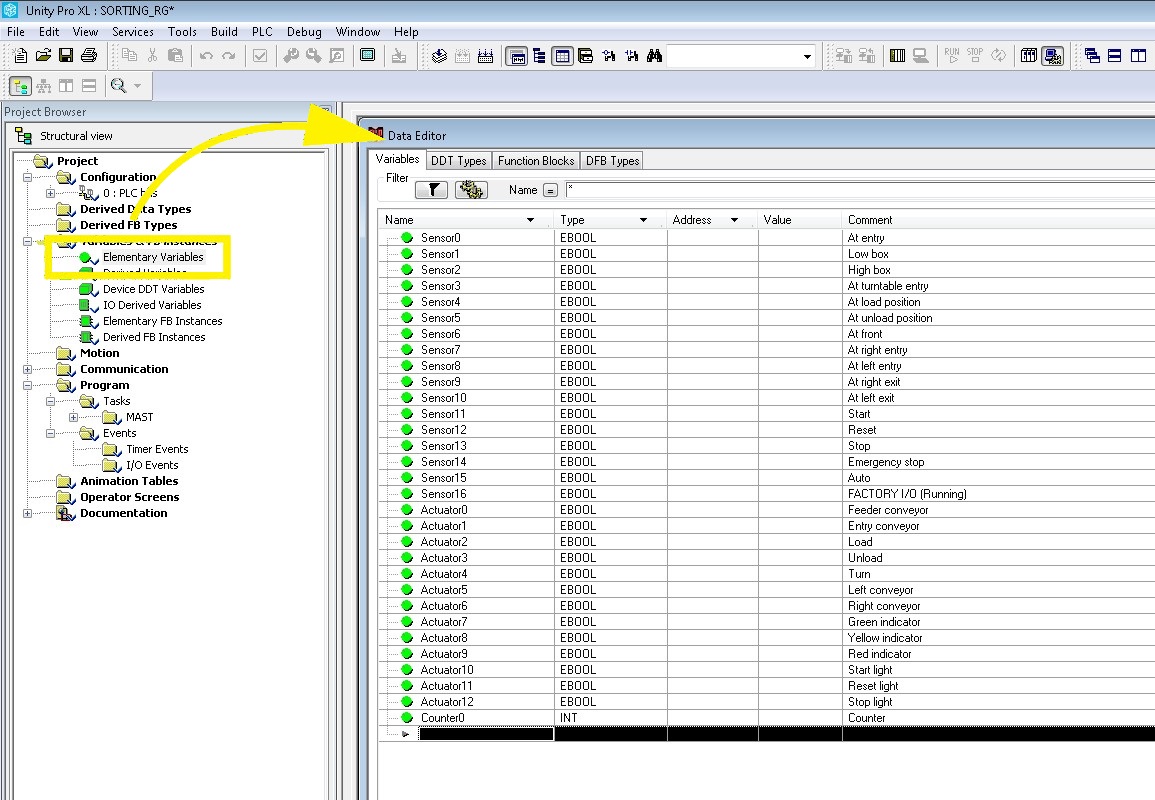
The project has been created and you are now ready to start writing the PLC program. But first, you must define the I/O variables that will be used.
-
Double Left-click on Elementary Variables and create 17 EBOOL variables named Sensor0 up to Sensor16. These will be the variables used for sensor values. On the Comment fields type in the name of the Factory I/O points they represent so you can easily relate one to another.
-
Next, create 13 EBOOL variables named Actuator0 up to Actuator12. These will be the variables used for actuators. As you did previously, fill the Comments fields with the name of the Factory I/O points they represent. At last, create 1 INT variable named Counter0 (which is to be used by the counter display).
-
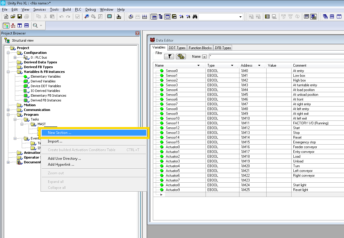
Create a section for the PLC code by Right-clicking on Program > Tasks > MAST > Sections and selecting New section...
-
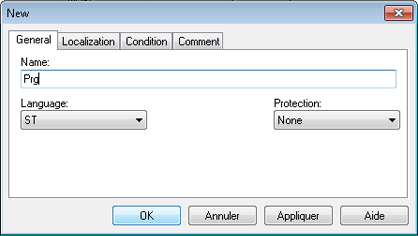
Give a name to the section (e.g. Prg) and choose a programming language (e.g. ST).
-
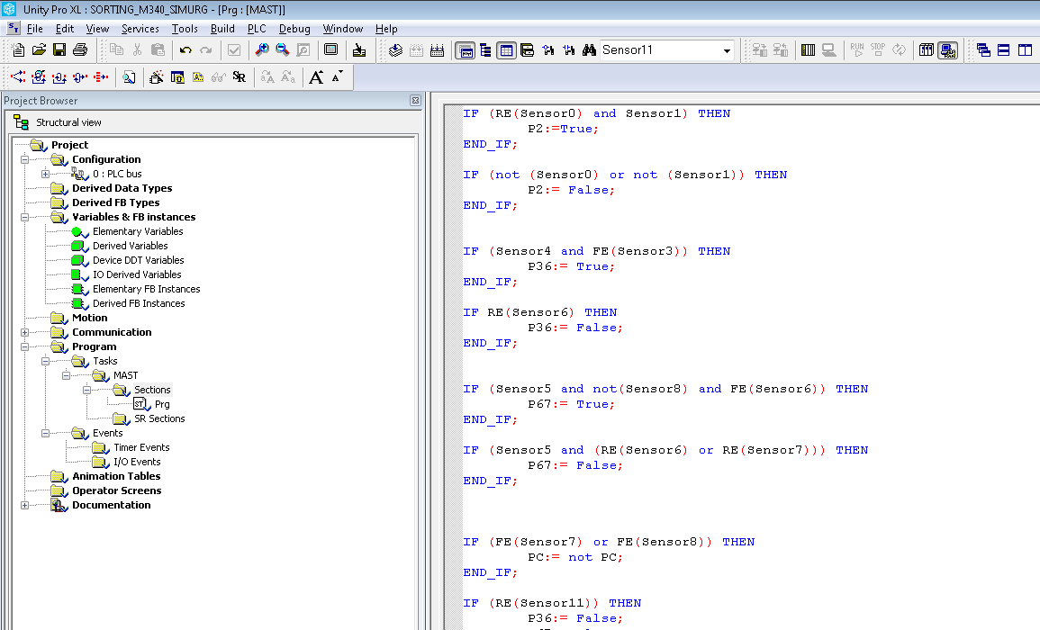
You can now start writing the PLC program using the programming language selected above. The next image shows an example of a program written in Structured Text.
-
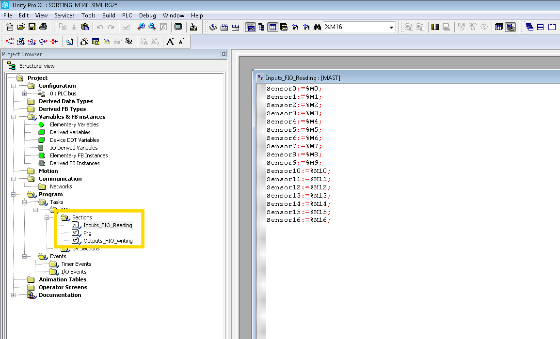
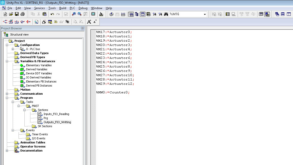
For Factory I/O to work together with Unity Pro you must assign memory values to internal variables. You do this by creating a new section called Inputs_FIO_Reading where values of memories %M0 up to %M16 are assigned to Sensor0 up to Sensor16 variables. You must do the same for actuator variables by creating an Outputs_FIO_Writing section and assigning the 13 actuators (%M17 up to %M29) and the Counter0 variable to an Int memory %MW. Note that Inputs_FIO_Reading should be placed first on the section tree so the latest sensor values are available when the program is executed. On the other hand, Outputs_FIO_Writing should be placed last, so actuator values are assigned to memories after the program is executed.
-
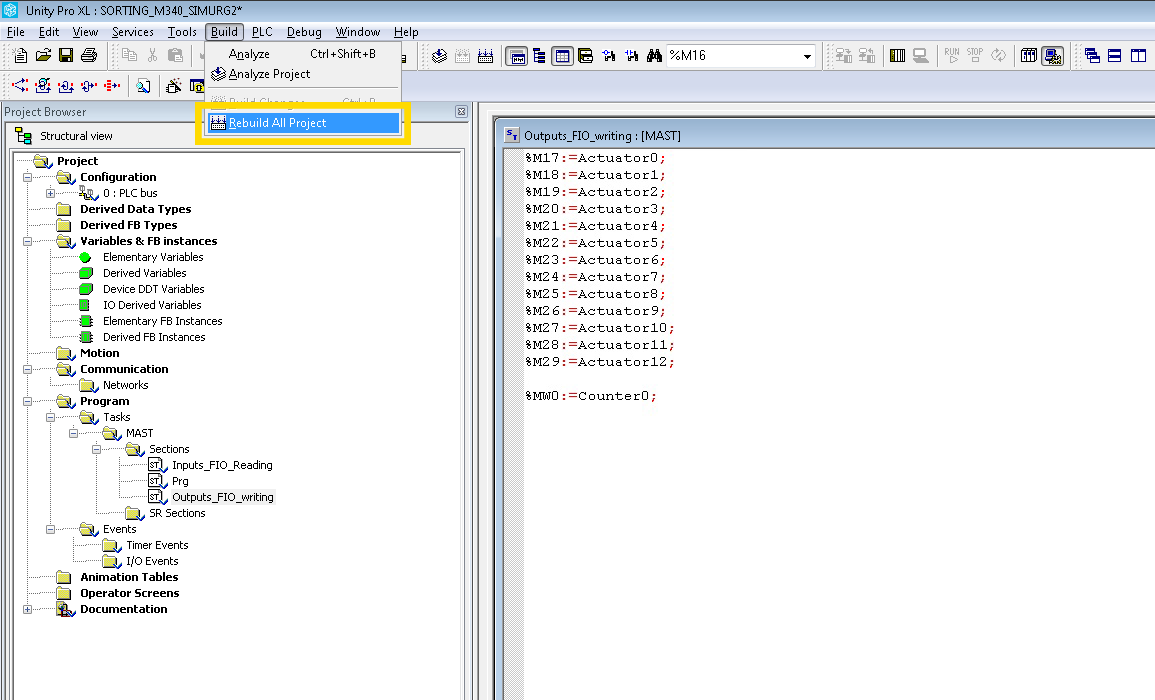
Build the project by clicking on Build > Rebuild All Project.
-
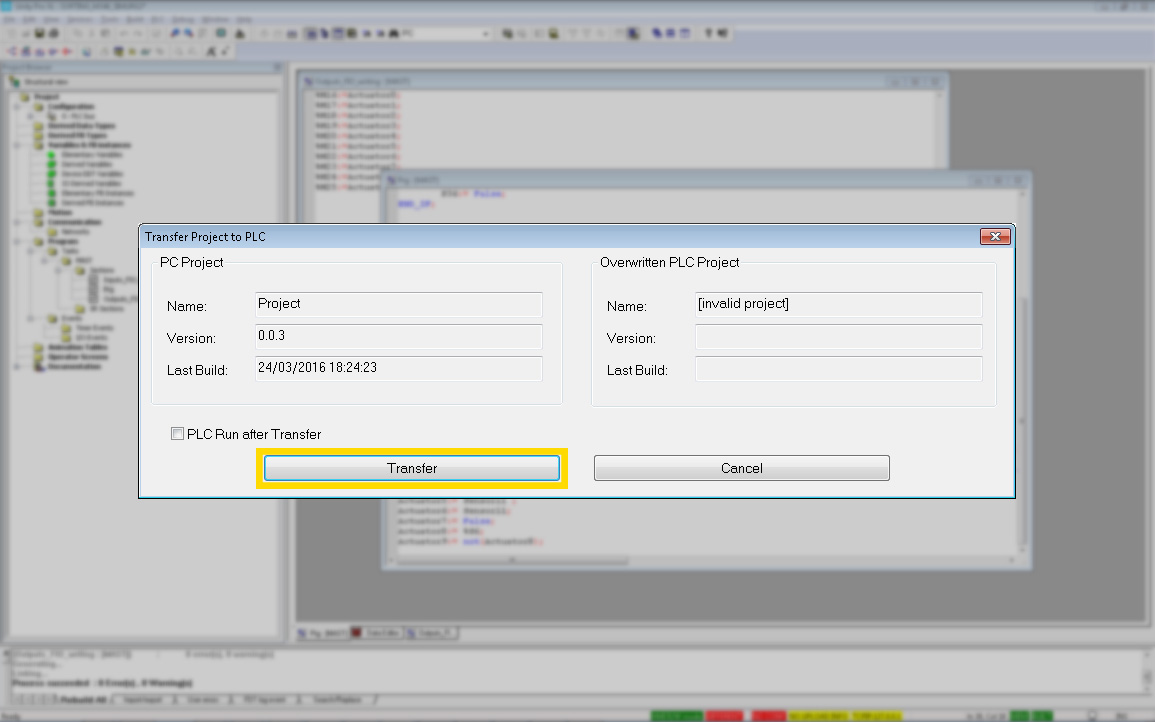
Select Simulation Mode by clicking on PLC > Simulation Mode. Next, connect to the soft PLC by clicking on PLC > Connect and download the program by clicking on PLC > Transfer Project to PLC. Click on Transfer.
-
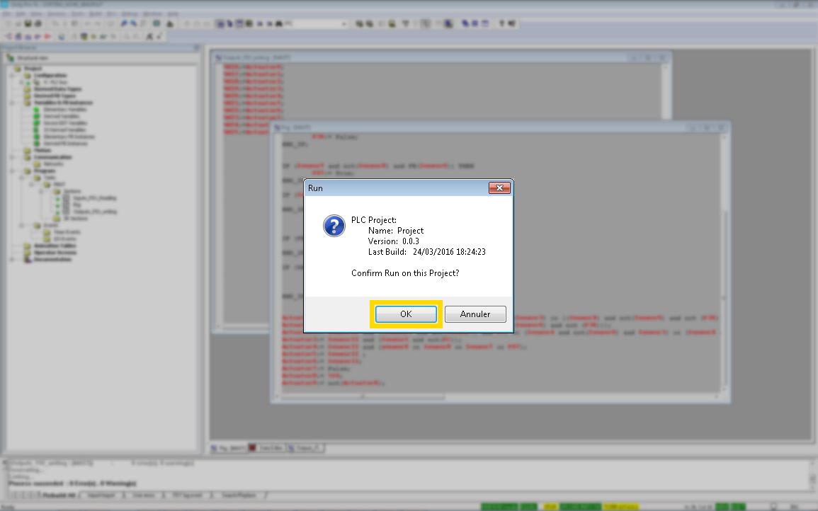
Now, switch the PLC to Run mode by clicking on PLC > Run. Click on OK.
-
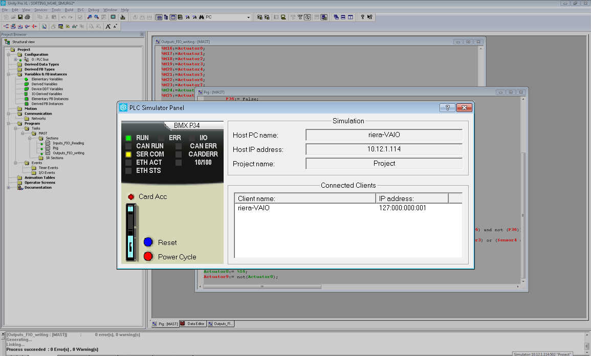
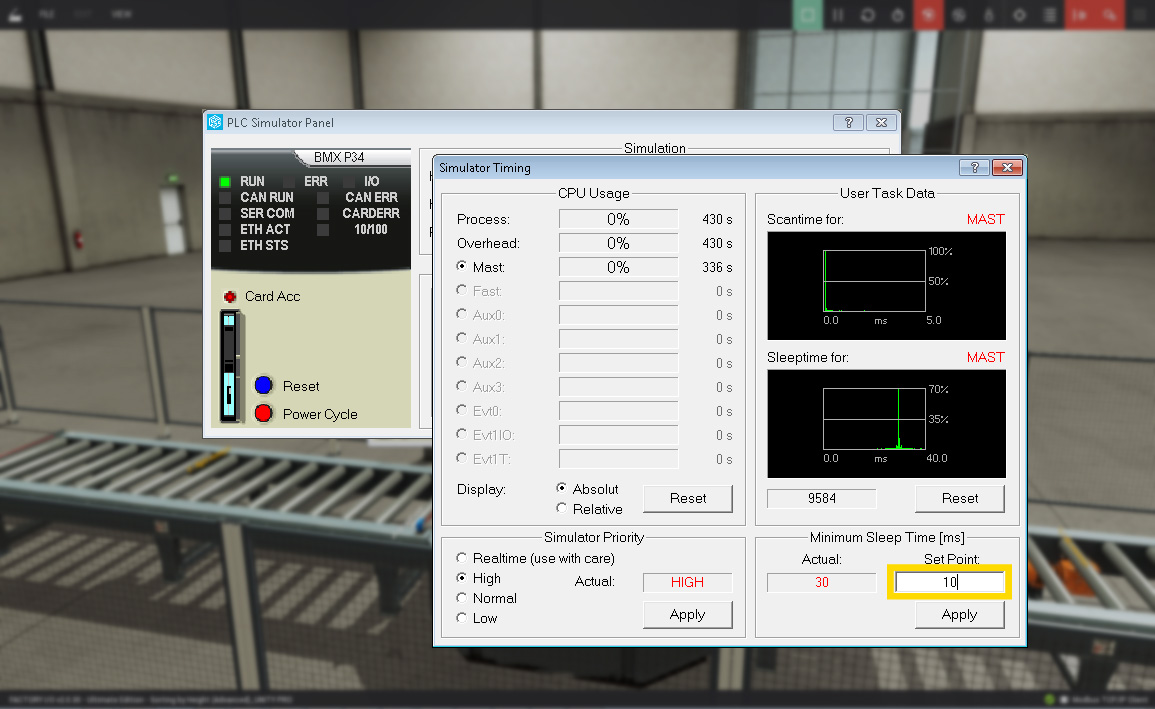
You should select a scan time of 10ms by Right-clicking on the soft PLC icon (taskbar) and selecting Timing...
-
Go back to Factory I/O, click on CONNECT and close the driver window (Esc).
-
Finally, switch to Run mode and select Auto by clicking on the selector.